Thermal Camera SDK 10.1.0
SDK for Optris Thermal Cameras
Loading...
Searching...
No Matches
Public API

Contents

Architecture

The following UML diagram illustrates the class structure of the public SDK API. All the details about the class members are omitted to ensure it is clear and easy to understand.

Class diagram detailing the class structure of the public API.

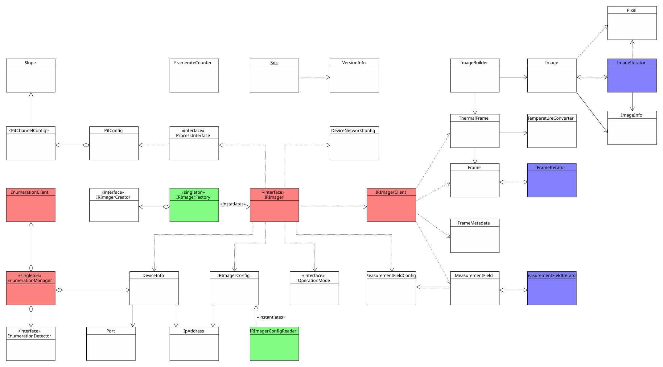
A number of design patterns are employed to make the API easy to use. They include but are not limited to

Observers (red)

The SDK features two Observer structures. The most important one is constituted by the IRImager interface and the IRImagerClient. Each IRImager instance represents a single thermal camera and its interface defines how you can interact with it. By registering a child class of the IRImageClient with the addClient() method you can receive processed thermal frames, flag states and other status information. To process this data implement the corresponding callback methods defined by the IRImagerClient in your child class.

The EnumerationManger uses the same pattern to inform EnumerationClient classes of newly attached or removed devices.

Both client classes feature empty default implementations for the callbacks they define. Therefore, you only need to override the callbacks that you need.

Factories (green)

Factories encapsulate the instantiation of classes. The public API features two such factories: The first one is the IRImagerFactory that creates objects of classes that implement the IRImager interface based on a provided string. By requesting a native instance you get an IRImager implementation that can interact with thermal cameras via USB and Ethernet.

The second factory loads a configuration files from the given path and returns an IRImagerConfig object with the read configuration values.

Iterators (blue)

The iterator classes are designed to offer a uniform and convenient way to iterate over the data values stored in Frame, ThermalFrame, MeasurementField and Image objects. However, they do not offer the best performance for this purpose particularly in programming languages that are supported via bindings.

For more details on efficient ways to access thermal and image data please refer to the sections Retrieving Thermal Data and Creating False Color Images.

Singletons

Both the IRImagerFactory and the EnumerationManager are Singletons. This means there can only be one object per class and per application. To access this object you have to call the static method getInstance().

Static Classes

Apart from the design patterns there is another important class: the static Sdk class. It contains the init() method required to initialize the SDK, methods to manipulate some SDK wide behavior and access to VersionInfo objects holding version and build information.

Thermal Data

As illustrated in the previous section, the SDK uses an Observer pattern to relay the latest thermal data to a client. This primarily happens via the following method of the IRImagerClient class (C++):

void onThermalFrame(const ThermalFrame& thermal, const FrameMetadata& meta);

The thermal data is encapsulated in an object of the ThermalFrame class while a FrameMetadata object holds its corresponding metadata. There are a few important things to note:

  • The method does only provide references (&) to these objects that grant access to their data. The references and the objects are only valid during the callback. If you wish to use the ThermalFrame data or the FrameMetadata outside the callback, you will have to make an explicit copy.

    Attention
    In C++ a simple assignment is enough. In any other language you have to use the clone() methods of the ThermalFrame and FrameMetadata classes to ensure an explicit copy is created.
  • The provided references are const. This means you can not manipulate the objects to which they are pointing to. You have only read access.

    Attention
    The const qualifier is typically not mirrored in the bindings of the other supported programming languages. Thus, it may appear that you can manipulate these objects but this will certainly lead to errors.
  • Keep your method implementation short because no further frames are processed while it is active.
Note
These observations also apply to the onMeasurementField() and onThermalFrameEvent() methods of the IRImagerClient class.

The ThermalFrame object contains the measured temperatures for each pixel in an internal format. These values are represented by unsigned 16 bit integers. You can convert the internal values into degree Celsius with the help of an TemperatureConverter object. Retrieve it for every ThermalFrame with the getConverter() method.

Attention
Do not use TemperatureConverter objects that you instantiated yourself but retrieve them from every ThermalFrame you process. This is necessary because the internal values differ depending which TemperaturePrecision is currently active.

You have multiple ways to access the thermal data that is internally stored in a one-dimensional array:

  • Use the getValue() methods to access the internal temperature values for individual pixels.
  • Use the getTemperature() methods to access the temperature in degree Celsius for individual pixels.
  • Use the getConstIterator() method to get an iterator that allows you iterate over the entire frame.

The iterator is convenient but does not offer the best performance particularly in programming languages that are supported via bindings. The most efficient ways to access the thermal data are:

C++
Use the getData() method to acquire a const pointer to the internal temperature value of the first pixel. All the values are stored in one continuous section of the memory like they would in a standard C array. As an alternative, you can use the copyDataTo() method.

The temperatures in degree Celsius can be acquired with copyTemperaturesTo() in the same way.

std::vector<unsigned int> data(thermal.getSize()); // Thermal data in internal format
std::vector<float> temperatures(thermal.getSize()); // Thermal data in degree Celsius
thermal.copyDataTo(data.data(), data.size());
thermal.copyTemperaturesTo(temperatures.data(), temperatures.size());

C#
Use the copyDataTo() method to copy the internal temperature values to a ushort[] array. Make sure it has at least the size returned by the getSize() method.

The temperatures in degree Celsius can also be copied to a float[] array via the copyTemperaturesTo() method. This array should at least have the size returned by getSize().

ushort[] data = new ushort[thermal.getSize()]; // Thermal data in internal format
float[] temperatures = new float[thermal.getSize()]; // Thermal data in degree Celsius
thermal.copyDataTo(data, data.Length);
thermal.copyTemperaturesTo(temperatures, temperatures.Length);

Python 3
Use the copyDataTo() method to copy the internal temperature values to a two-dimensional NumPy array with the shape (getWidth(), getHeight()) and the data type uint16.

The temperatures in degree Celsius can also be copied to a two-dimensional NumPy array via the copyTemperaturesTo() method. This array should have the shape (getWidth(), getHeight()) and the data type float32.

data = np.empty((thermal.getWidth(), thermal.getHeight()), dtype=np.uint16) # Thermal data in internal format
temperatures = np.empty((thermal.getWidth(), thermal.getHeight()), dtype=np.float32) # Thermal data in degree Celsius
thermal.copyDataTo(data)
thermal.copyTemperaturesTo(temperatures)
Note
These remarks also apply to the thermal data stored in MeasurementField objects.

False Color Images

You can easily convert a ThermalFrame into a false color image with the help of an ImageBuilder object. The resulting images have three channels: red, blue and green. Each channel has a color depth of 8 bits. The color values are stored in a continuous one-dimensional array. When setting up the ImageBuilder there are few things to consider:

  • The ColorFormat defines the sequence in which the individual color values for each pixel are stored in the image array. If set to RGB, the value for red will have the lowest index and the value for blue will have the highest. With BGR things are the other way around.

    Note
    Not all libraries or programming languages may interpret RGB and BGR this way.
  • The WidthAlignment specifies whether the size of each row/line in the resulting image should adhere to a specific alignment. For example the FourBytes alignment ensures that the size of every row/line in bytes is a multiple of four. If this is not the case out of the box, padding bytes will be added at the end of each line. Some libraries depend on a certain alignment to efficiently read image data.
  • The ColorPalette defines with what set of colors the different temperatures are represented. Refer to the API documentation of the ColorPalette enum to get an idea what options are available.
  • The PaletteScalingMethod specifies how the ColorPalette gets applied to the temperature spectrum found in a ThermalFrame.

Once the ImageBuilder object is set up you can set the ThermalFrame to convert with the setThermalFrame() method. Trigger the conversion with convertTemperatureToPaletteImage() and access the result with getImage(). The image data is encapsulated in an Image object.

Attention
The getImage() method returns only a reference to the Image object that grants read access. If you want to retain a copy in languages other than C++, use the clone() method to force an explicit copy. Keep in mind that you can not manipulate the referenced Image object even if the API of the bindings may suggest it.

You can access the image data in different ways:

  • Use the getPixel() methods to get a Pixel object containing the color values.
  • Use the getConstIterator() method to get an iterator that enables you to iterate over the image pixel by pixel.

The iterator is more convenient than the ones for the thermal data because you do not need to worry about the order of the color values and potential padding bytes. It shares, however, the same downsides. Therefore, the SDK provides more efficient ways to access the image data:

C++
Use the getData() method to acquire a const pointer to the color value array. All the values are stored in one continuous section of the memory like they would in a standard C array. As an alternative, you can use the copyDataTo() method. The following example uses the shortcut methods provided by the ImageBuilder class.

std::vector<unsigned char> image(imageBuilder.getImageSizeInBytes());
imageBuilder.copyImageDataTo(image.data(), image.size());

C#
Use the copyDataTo() method to copy the color values to a byte[] array. Make sure it has at least the size returned by the getSizeInBytes() method. The following listing utilizes the shortcut methods offered by the ImageBuilder class.

byte[] image = new byte[imageBuilder.getImageSizeInBytes()];
imageBuilder.copyImageDataTo(image, image.Length);

Python 3
Use the copyDataTo() method to copy the color values to a three-dimensional NumPy array with the shape (getWidth(), getHeight(), 3) and the data type uint8. The example code below makes use of the shortcut methods of the ImageBuilder class.

image = np.empty((image_builder.getHeight(), image_builder.getWidth(), 3), dtype=np.uint8)
image_builder.copyImageDataTo(image)
Attention
A downside of these more efficient ways is that you have to take care of the color value order and of potential padding bytes at the end of every image row/line yourself.
Note
The ImageBuilder offers the shortcut methods copyImageDataTo() and getImageSizeInBytes() that allow you direct access the data of the Image object.

Measurement Fields

Measurement fields are sub-sections of the thermal frame that can be processed with a different set of radiation parameters (emissivity, transmissivity and ambient temperature). The minimum, maximum and mean temperatures in degree Celsius are calculated for every measurement field by default and can be accessed through the corresponding member functions of the MeasurementField class.

Measurement fields are created by providing their configuration in either the configuration file or by passing an instance of the MeasurementFieldConfig class to the addMeasurementField() method of the IRImager. This method returns an integer representing the index of the measurement field. This index starts at zero and is incremented with each added field reflecting their creation order. The fields in the configuration will always be added first. The index can be used to refer to a specific measurement field.

Note
Internally the SDK uses an unique auto assigned ID to identify the different measurement fields.

At the moment the SDK only supports rectangular measurement fields. They are defined by their width and height in pixels and by the position of their upper left corner. Multiple overlapping and/or equal fields can exist at the same time.

Attention
Due to limitations imposed by the algorithm used to process measurement fields a field can not cover a one pixel wide margin at the edges of thermal frame. Trying to create such a field will result in an error or and exception.
Defining a rectangular measurement field within a thermal frame.

The mode of the measurement field specifies which of the three available temperatures (minimum, maximum, mean) is returned by the getDataPoint() method of the MeasurementField class. The option is primarily used by the SDK to identify which data point should be output on a Process Interface channel. This mechanism can of course also be utilized by SDK clients.

Once the SDK finished processing a measurement field it informs all registered IRImagerClients via their onMeasurementField() callback method. Please note, that this method just provides a constant reference to the corresponding MeasurementField object. This reference only grants read access and is only valid during the callback. For details about how to extract the thermal data or how to retain a copy please refer to the section about Thermal Data.

Process Interface (PIF)

The Process Interface can be setup via the configuration file. At runtime you can access it through the methods exposed by the ProcessInterface interface. This is, however, only possible when the IRImager has an active camera connection. If no connection is established, calls of the getPif() methods will result in a SDKException.

Attention
The IRImager::getPif() methods return a reference to the implementation object of the ProcessInterface. This reference is only valid during an active camera connection. Therefore, take great care when you are retaining a copy of this reference!

The ProcessInterface allows you to get and set the configuration for an entire process interface or just for its individual channels. By providing coherent configurations instead of single options at a time the SDK can better ensure their overall validity and consistency .

Device

Type

The configuration requires you to specify the type of PIF you wish to use. The SDK will then check your choice against the PIF type reported by the camera firmware. Depending on the camera type this will either be

  • the set PIF type in the on-device configuration (Xi 80, Xi 410(MT), Xi 1M)
  • the detected PIF type (all other cameras)

Depending on the situation the SDK will try set the desired device. This can yield the following outcomes:

  • The set PIF type is actually connected. Then the SDK will apply the channel configurations.
  • A SDKException, if the desired PIF type is not compatible with the camera.
  • A SDKException, if the set type is Proprietary or TemperatureProbe and an actual PIF is connected.
  • If a PIF type was set but no PIF is actually connected, the SDK will use the None type and will ignore all channel configurations.
  • If a PIF type was set but a different type is connected, the SDK will assume the reported type and will try to apply all the specified channel configurations. This, however, may fail because not all analog output modes are supported by all PIF devices.
Note
You can set the PIF type to Automatic. The SDK will then automatically use the type reported by the firmware. In this case it will also try to apply all specified channel configurations. This can, however, fail because of unsupported analog output modes.

For more details please refer to configuration file documentation or to the Process Interface (PIF) chapter.

Count

When using stackable PIFs you need to set the number of PIF devices you wish to use. In all other cases the SDK can derive this count from the set PIF device type.

Note
A maximum of three stackable PIFs can be attached to same camera at the same time.

The number of stackable PIFs has to be defined either in the configuration file or via the deviceCount member variable in the PifConfig class when using the setConfig() method of the ProcessInterface.

Attention
The device count specifies how many stackable PIFs can be accessed and configured through the SDK. The count of actually connected PIFs can be lower!
Note
The SDK will not be able to detect more connected stackable PIFs than specified by this device count.

This behavior allows clients to configure PIFs without the need to connect them to the camera. At the moment, however, this is pointless because the SDK does not support autonomous settings that would retain the set configuration on-device. Currently, the configuration is lost when the camera loses power.

Channels

Depending on the used PIF different channel types are available:

  • analog inputs can read input voltages between 0 - 10 V.
  • digital inputs can read binary voltage signals.
  • analog outputs can potentially output signals in the output modes 0 - 10 V, 0 - 20 mA and 4 - 20 mA depending on the type of process interface.
  • digital outputs can output binary voltage signals.
  • fail safe can output a level based voltage signal indicating whether the camera and the processing pipeline of the SDK is working properly.
Note
The SDK uses the following abbreviations to mark resources for the specific channel types, like classes or enums:
  • Ai - analog inputs
  • Di - digital inputs
  • Ao - analog outputs
  • Do - digital outputs
  • Fs - fail safe

Addressing

The individual channels are addressed by a pair of indices: [deviceIndex, pinIndex]. The deviceIndex refers to the physical process interface on with the pins for the desired channel are located. It is only relevant for stackable PIFs. In all other cases the deviceIndex is 0.

The pinIndex identifies the actual pins on the specified PIF device that correspond with the desired channel.

To better understand the addressing of the channels please consider the setup shown in the figure below: Three stackable PIFs are configured but only two are actually connected to the camera (the one not connected is grayed out).

Stackable process interface example.

In this case the deviceIndex can be in [0, 2] and the pinIndex can be in [0, 1]. Thus, manipulating the pins 0 and 1 on the PIF device 2 is possible but will yield any tangible effects.

The properties of this addressing schema are also reflected in the getter methods for the device and channels counts provided by the ProcessInterface. Their differences are best understood with the above example in mind:

Devices

  • getActualDeviceCount() returns the number of actually connected devices. Example: 2.
  • getConfigurableDeviceCount() returns the number configurable devices. Example: 3.
Note
On non-stackable PIFs these methods yield the same values.

Channels (XX denotes the channel type)

  • getActualXXCount() returns the count of all XX channels on actually connected devices. Example: 2 * 2 = 4.
  • getConfigurableXXCount() returns the count of all XX channels on configurable devices. Example: 3 * 2 = 6.
  • getXXCountPerDevice() returns the count of XX channels per individual device. Example: 2.
Note
On non-stackable PIFs these methods yield the same values.

The fail safe channel is an exception. If available, there will always be only one of it. Even in the case of multiple stackable PIFs that each have separate pins for this channel. In this case these pins will all output the same signal.

Configuration

Each available channel on a PIF can be configured to have a specific functionality by assigning it a mode. This can either be done with the help of the configuration file or through the configuration setter methods exposed by the ProcessInterface. With them you can either set the configuration for the entire device at once or just for a single channel.

The most important configuration option that specifies the desired functionality is the mode. Depending on your chosen mode you may need to provide additional configuration parameters. Each channel type has its own configuration class that encapsulates all the potential parameters required by the different modes:

  • analog inputs - PifAiConfig
  • digital inputs - PifDiConfig
  • analog output - PifAoConfig
  • digital output - PifDoConfig
  • fail safe - PifFsConfig

You can either refer to the API or configuration file documentation for a comprehensive explanation of their effects. In order to make it easy to generate correct configurations all the configuration classes listed above feature a static create method for each supported mode. If you want to output a frame synchronization signal with a pulse height of 7.5 V on the analog output channel [0, 1], you will be able to generate the required configuration object in C++ as follows:

auto aoConfig = PifAoConfig::createFrameSync(0, 1, PifAoOutputMode::_0_10V, 7.5);

To apply this configuration you can either

  • call setAoConfig(aoConfig) from the ProcessInterface to adjust a single channel configuration or
  • add it to an instance of the PifConfig class

    PifConfig pifConfig;
    ...
    pifConfig.analogOutputs.push_back(aoConfig);

    and call setConfig(pifConfig) of the ProcessInterface to set the overall PIF configuration.

Note
All channels that do not have an explicit configuration in a PifConfig object are set to the mode off.

You can also use the getter methods for the overall PIF configuration or for the individual channel configurations to get objects encapsulating their current state. You can then update them by adjusting the values of their member variables and passing them back to their respective setter methods.

The following modes are unique, meaning they can only be applied once per PIF:

  • AmbientTemperature
  • Emissivity
  • FailSafe
  • FlagControl
  • FrameSync
  • InternalTemperature
Note
The fail safe channel can be activated regardless of a PIF output channel set to FailSafe mode.

Output Values

Aside from letting the SDK or camera firmware generate signals on the output channels you can also do this manually. To this end, you have to set the desired output channel to the mode ExternalCommunication. For the analog output channel [0, 1] this could be done in C++ as follows:

setAoConfig(PifAoConfig::createExternalCommunication(0, 1, PifAoOutputMode::_0_10V));

If successful you can now set an output voltage of 5.5 V on this channel by calling

setAoValue(0, 1, 5.5);

from the ProcessInterface.

Note
The provided output value will automatically be clipped to the limits the configured output mode.

The same approach applies to digital outputs. Here a value of true generates a high signal and a value of false a low signal.

Attention
If you try to call setAoValue() or setDoValue() without setting the respective channel mode to ExternalCommunication, the SDK will throw an exception. In this way the SDK prevents you from meddling with and potentially disrupting other output channel functionality.

Input Values

The currently read values on the input channel pins can be accessed at any time through the FrameMetadata object provided by the onThermalFrame() callback of the IRImagerClient interface.

Note
You will be able to access the input values even if the respective channel mode was set to off.

Use the method

  • getPifAiValue(deviceIndex, pinIndex) to get the currently read voltage on the corresponding analog input pins.

    Note
    There are a few points to keep in mind when reading analog input voltages
    • Analog inputs can read voltages between 0 V and 10 v.
    • Voltages above 10 V register as 10 V with the PIF and consequently the SDK.
    • The measured voltages are subject to a calibration. This can include a fixed offset. As a result, the SDK can report voltages slightly above 10 V as well as voltages slightly above 0 V when the pins are pulled to ground.
    • The SDK may report voltages above 0 V when the pins are floating.
  • getPifDiValue(deviceIndex, pinIndex) to get a boolean indicating whether the voltage signal on the digital input pins is high (true) or low (false).

The FrameMetadata object contains inputs values for all configurable PIF devices regardless of whether they are connect or not.

Attention
The input values for channels with pins on a stackable PIF that is configurable but is not connected are invalid! In the example this would be the case for input channels using the pins 0 and 1 on PIF 2.

The FrameMetadata also contains the count of configurable and actually connected PIFs that can be accessed via its getPifActualDeviceCount() and getPifConfigurableDeviceCount() methods. With their help you can easily identify the deviceIndex values that refer to valid input data:

0 <= deviceIndex < getPifActualDeviceCount()

Client Fail Safe

The fail safe mechanism of the SDK continuously monitors various conditions which indicate that the camera and the processing chain of the SDK are working properly. If one of these conditions fails, the fail safe will be deactivated. As result, the SDK will no longer publish a heart beat signal on respectively configured PIF output or fail safe channels.

By calling

interruptFailSafe(true, "GUI thread crashed.");

of the IRImager interface clients can actively fail one of those conditions and thus deactivate the fail safe and its signal. The condition can be restored to a passing state when the same method is called as follows:

setClientFailSafeActive(false, "GUI thread restored.");

This will, however, not necessarily activate the fail safe signal, if other required conditions still fail.

For more details please refer to the Fail Safe chapter.