 |
Thermal Camera SDK 11.3.0
SDK for Optris Thermal Cameras
|
|
Thermal Camera SDK 11.3.0
SDK for Optris Thermal Cameras
|
The SDK utilizes a number of important files to store device settings, determine device capabilities and gather data required for processing. Some files are generated by the SDK (configuration, dynamic dead pixel) and others are provided by Optris (calibration, format definitions and normalization tables). Regardless of their source the SDK needs to be able to locate them on the filesystem. In general it will probe the following directories in the sequence listed below:
Clients can set a custom user data directory with the help of the Sdk::setCustomDataDirectory() method. This replaces the default locations of
<User AppData>\Roaming\Imager\ on Windows and~/.config/optris/ on Linux.When specifying the directory path the following symbols/variables are supported:
~, %USERPROFILE% refer to ~/ on Linux and <User Home>/ on Windows.%APPDATA% refers to ~/.config/ on Linux and <User AppData>/Roaming/ on Windows.Relative paths are not supported. You can either use / as system independent directory separator or utilize system dependent ones like / for Linux and \ on Windows.
The SDK automatically generates the following subdirectories:
Cali - for the calibration files.Configs - for the configuration files.Logs - for the log files.DynamicDeadPixels - for detected dynamic dead pixels. The directory only appears after a successful connection to a device during which dead pixels were detected.All other folders mentioned below need to be created manually (e.g. Cali/Norm or the color palette folder palettes).
The SDK data directory is
<SDK Install Directory>\ on Windows/usr/share/otcsdk/ on LinuxBoth of them have in common that ordinary users only have read access. This is not an issue because the SDK only searches this directory for files that are useful for all SDK client applications like the format definitions.
The configuration file defines the device specific settings for the camera and optionally attached processing interfaces.
File Name
<Serial Number>.xml
How To Get It
The configuration file is automatically generated by the SDK when connecting to a new camera. The file is placed in the user settings directory. Depending whether a custom data directory was set the resulting file is located at:
<Custom Data Directory>/Configs/<User AppData>\Roaming\Imager\Configs\ on Windows~/.config/optris/Configs/ on LinuxSDK Search Hierarchy
<Custom Data Directory>/Configs/<User AppData>\Roaming\Imager\Configs\ on Windows~/.config/optris/Configs/ on LinuxThe configuration is split into several sections for clarity. These sections should be included between the <imager> tags in the XML configuration file in the sequence they are discussed here.
| Type | Constraint | Default | Required | Availability |
|---|---|---|---|---|
| int | > 0 | - | yes | >= v1 |
Configuration file version. Its value is used by the SDK to determine how to parse the configuration file.
| Type | Constraint | Default | Required | Availability |
|---|---|---|---|---|
| string | - | - | no | >= v1 |
Version of the SDK that generated the configuration file. Currently, not parsed by the SDK.
| Type | Constraint | Default | Required | Availability |
|---|---|---|---|---|
| int | > 0 | 0 | yes | >= v1 |
The serial number identifies the device the configuration file applies to. The cameras typically have a sticker with their serial number on it. Sometimes it also features the serial number of the optics.
| Type | Constraint | Default | Required | Availability | Remarks |
|---|---|---|---|---|---|
| string | usb | yes | >= v1 | case insensitive |
Defines the connection interface that the SDK should use to communicate with the device. Natively, the SDK supports the following interfaces:
usbethernet (respectively network connection)For more details about the the communication between the SDK and the device please refer to the chapter Device Communication.
ethernet interface the settings for the IP address and the port should align with the ones set on the device with the help of the PixConnect or the otc_configure_ethernet commandline tool.| Type | Constraint | Default | Required | Availability |
|---|---|---|---|---|
| string | IP v4 address in dot notation | 192.168.0.101 | no | >= v1 |
When using the ethernet interface the IP address refers to the IP v4 address of the device.
| Type | Constraint | Default | Required | Availability |
|---|---|---|---|---|
| int | >= 0 | 50101 | no | >= v1 |
In case of the ethernet interface this option refers to the local port on which the SDK can receive the frame data from the device.
| Type | Constraint | Default | Required | Availability |
|---|---|---|---|---|
| bool | - | true | no | >= v1 |
If set to true, the SDK will only accept and process data packages from the IP address specified above.
| Type | Constraint | Default | Unit | Required | Availability |
|---|---|---|---|---|---|
| int | >= 0 | 10 | seconds | no | >= v1 |
Specifies the time in seconds until a device connection is considered to have timed out because no frame data was being received. When a timeout occurs the SDK will trigger the onConnectionTimeout() callback of the IRImagerClients.
| Type | Constraint | Default | Required | Availability |
|---|---|---|---|---|
| int | > 0 | 5 | no | >= v1 |
Specifies the number of buffers that the subsystems receiving the raw frame data should use (DirectShow, V4L2, etc.). This option does not affect the actual size the individual buffers. That is determined by the used video format.
These options define what processing outputs should be generated by the SDK.
| Type | Constraint | Default | Required | Availability |
|---|---|---|---|---|
| bool | - | false | no | >= v3 |
If set to true, raw unprocessed frame data is provided via the IRImager::onRawFrame() callback. If false, this callback is not triggered.
| Type | Constraint | Default | Required | Availability |
|---|---|---|---|---|
| bool | - | true | no | >= v3 |
If set to true, processed thermal frame data is provided via the IRImager::onFrame() callback. If false, the returned ThermalFrame is empty.
| Type | Constraint | Default | Required | Availability |
|---|---|---|---|---|
| bool | - | true | no | >= v3 |
If set to true, measurement fields are processed and the result are available via the IRImager::onFrame() callback. If false,
measurement_field mode are updated| Type | Constraint | Default | Required | Availability |
|---|---|---|---|---|
| int | > 0 | 1 | no | >= v3 |
Sets the maximum number of processing result buffers that are pooled for reuse to avoid unnecessary allocations.
The processing pipeline reuses the same objects to store its results. This setting specifies the maximum number of these objects that can exist at the same time. If the client callbacks handling the processing results are too slow, the SDK will start to override already existing results. This effectively results in frame drops.
Buffers are only added as needed.
If set to 0, the maximum pool size will be set to 1.
| Type | Constraint | Default | Unit | Required | Availability |
|---|---|---|---|---|---|
| int | >= 0 | 0 | degrees | no | >= v1 |
Identifies the optics used by the device via their field of view in degrees.
| Type | Constraint | Default | Required | Availability |
|---|---|---|---|---|
| string | - | no | >= v1 |
Sometimes specifying the field of view is not enough to unambiguously identify the optics. In such a case an additional text is used to differentiate between them.
0 and the text is left blank, the SDK will automatically choose the first optics specified in the calibrations.| Type | Constraint | Default | Required | Availability | Remarks |
|---|---|---|---|---|---|
| string | normal | no | >= v3 | case insensitive |
Identifies the mode with which the radial distortion correction (RDC) should be performed. This has only an effect if the required parameters are provided by the calibration. The available modes are:
off - radial distortion correction is disabled.normal - radial distortion correction is perform in normal mode.wide - radial distortion correction is perform in wide mode.| Type | Constraint | Default | Required | Availability |
|---|---|---|---|---|
| bool | - | true | no | >= v2 |
If true, a size of source correction is automatically performed for devices whose calibration data features the necessary information.
| Type | Constraint | Default | Unit | Required | Availability |
|---|---|---|---|---|---|
| int | - | 0 | degree Celsius | no | >= v1 |
Defines the non-extended lower limit of the temperature range in degree Celsius.
| Type | Constraint | Default | Unit | Required | Availability |
|---|---|---|---|---|---|
| int | - | 0 | degree Celsius | no | >= v1 |
Defines the non-extended upper limit of the temperature range in degree Celsius.
0, the SDK will automatically choose the first temperature range defined in the calibrations that is available for the configured optics.Please refer to the Supported Camera section to get a list of all the available temperature ranges for the different devices.
| Type | Constraint | Default | Required | Availability |
|---|---|---|---|---|
| bool | - | false | no | >= v1 |
Some temperature range can be extended beyond the limits specified with min and max. If set to true, this extension will be enabled when available.
| Type | Constraint | Default | Required | Availability |
|---|---|---|---|---|
| bool | - | true | no | >= v1 |
Some temperature range for some devices feature a higher temperature measurement precision. If set to true, the SDK will automatically use the higher precision when available.
| Type | Constraint | Default | Unit | Required | Availability |
|---|---|---|---|---|---|
| int | >= 0 | 0 | pixel | no | >= v1 |
Specifies the width of the output thermal frame in pixels.
| Type | Constraint | Default | Unit | Required | Availability |
|---|---|---|---|---|---|
| int | >= 0 | 0 | pixel | no | >= v1 |
Defines the height of the output thermal frame in pixels.
| Type | Constraint | Default | Unit | Required | Availability |
|---|---|---|---|---|---|
| int | >= 0 | 0 | Hz | no | >= v1 |
Specifies the framerate in Hz with with which the device provides the thermal frames.
0, the SDK will automatically choose the first video format that is available for the configured optics and temperature range.Please refer to the Supported Camera section to get a list of all the available video formats for the different devices.
| Type | Constraint | Default | Unit | Required | Availability |
|---|---|---|---|---|---|
| float | - | -1. | Hz | no | >= v1 |
Sets the rate in Hz to which the SDK should limit the output of thermal frames. This option does not affect the rate which the device provides frame data. This rate is set by the firmware of the device and can not be changed by the SDK.
Leave it blank or set it to a negative value to deactivate this option.
All devices feature an internal shutter flag that can completely block the field of view of the sensor chip. It has to be closed periodically to enable the SDK to compensate for drifting temperature measurements.
The SDK uses readings of internal temperature probes of the device to determine when to start a flag cycle by closing the shutter flag. During this cycle the SDK updates the temperature drift compensation.
| Type | Constraint | Default | Required | Availability |
|---|---|---|---|---|
| bool | - | true | no | >= v1 |
If set to true, the shutter flag will automatically be controlled by the SDK.
| Type | Constraint | Default | Unit | Required | Availability |
|---|---|---|---|---|---|
| float | >= 0. | 12. | seconds | no | >= v1 |
Defines the minimum amount of time in seconds that has to pass after a completed flag cycle before a new one can be triggered.
| Type | Constraint | Default | Unit | Required | Availability |
|---|---|---|---|---|---|
| float | >= 0. | 0. | seconds | no | >= v1 |
Specifies the maximum amount of time in seconds that can pass before after a completed flag cycle before a new one is forced. Set it to 0 to deactivate this feature.
All devices feature an internal heating for the sensor chip. For some devices the sensor chip needs to be heated to a specific temperature so that the provided calibrations are correct.
| Type | Constraint | Default | Required | Availability | Remarks |
|---|---|---|---|---|---|
| string | floating | no | >= v1 | case insensitive |
Defines how the sensor chip should be heated. The available modes are:
floating - The heating is deactivated.auto - The sensor chip is heated to the temperature specified in the calibrations.fixed - The sensor chip is heated to a fixed temperature.| Type | Constraint | Default | Unit | Required | Availability |
|---|---|---|---|---|---|
| float | >= 0. | 40. | degree Celsius | no | >= v1 |
Specifies the temperature in degree Celsius the sensor chip should be heated to in the fixed heating mode.
Devices of the Xi series feature an internal motor that can be used to adjust the focus of the optics. For all other devices this has to be done manually.
| Type | Constraint | Default | Unit | Required | Availability |
|---|---|---|---|---|---|
| float | - | -1. | percent | no | >= v1 |
Specifies the focus motor position in percent ([0., 100.]). Leave it blank or set it to a negative value, if the position should not be adjusted.
The radiation parameters specified here affect the overall thermal frame. The radiation parameters for measurement fields are defined in their respective configurations.
| Type | Constraint | Default | Required | Availability |
|---|---|---|---|---|
| float | [0.01, 1.1] | 1. | no | >= v1 |
Defines the emissivity for the thermal frame.
| Type | Constraint | Default | Required | Availability |
|---|---|---|---|---|
| float | [0.01, 1.1] | 1. | no | >= v1 |
Specifies the transmissivity for the thermal frame.
| Type | Constraint | Default | Unit | Required | Availability |
|---|---|---|---|---|---|
| float | - | -100. | degree Celsius | no | >= v1 |
Specifies the ambient temperature for the thermal frame in degree Celsius. Leave it blank or set it to value equal or less than -100. to force the SDK to estimate the ambient temperature based on internal temperature probe readings.
The fail safe mechanism of the SDK provides a heart beat signal on process interface outputs indicating that the camera and the processing chain are working correctly. The fail safe can be activated by failing one of the following conditions:
For more details refer to the Fail Safe chapter.
| Type | Constraint | Default | Required | Availability |
|---|---|---|---|---|
| bool | - | true | no | >= v2 |
If set to true, flag timeouts will trigger the fail safe, if they cause enough flag cycles to fail.
| Type | Constraint | Default | Required | Availability |
|---|---|---|---|---|
| int | >= 0 | 0 | no | >= v2 |
Determines the maximum number of flag cycles that are allowed to fail due to flag timeouts before the fail safe is triggered.
| Type | Constraint | Default | Required | Availability |
|---|---|---|---|---|
| bool | - | true | no | >= v2 |
If set to true, the fail safe will be triggered, if the end points of the processing chain are not reached within a certain time frame.
In this section you can specify an arbitrary number of alarm channels. Each channel receives numeric values, e.g. temperatures, from a single input source, compares it to the configured ranges and raises an alarm if the value falls outside of those ranges. State changes of an alarm channel are always routed to the clients via the IRImagerClient::onAlarm() callback. Additionally, Active alarms can be combined into a CompositeAlarm and routed to PIF output channels.
For more detailed explanations please refer to the Alarms chapter.
You have the following options when defining an alarm channel within the <channels> tags above:
With the individual PIF output channel specified as follows:
| Type | Constraint | Default | Required | Availability |
|---|---|---|---|---|
| string | - | no | >= v3 |
Sets the name of the alarm channel. It does not have to be unique.
| Type | Constraint | Default | Required | Availability | Remarks |
|---|---|---|---|---|---|
| string | internal_temperature | no | >= v3 | case insensitive |
Specifies the inputs source from which the alarm channel should receive numeric values to be compare against the configured alarm ranges. The following inputs are available:
internal_temperature - internal device temperature in °C.chip_temperature - sensor chip temperature in °C.measurement_field - statistical value from a processed measurement field.uncommitted_value - uncommitted values generated from an analog PIF input channel.This section is only relevant if the input measurement_field was chosen.
| Type | Constraint | Default | Required | Availability |
|---|---|---|---|---|
| int | [0, count of configured measurement fields) | 0 | no | >= v3 |
Identifies the measurement field whose data point should be output. The index 0 refers to the first measurement field specified in the configuration and adheres to the sequence in which they are defined.
If there are three measurements fields configured, then 0 refers to the first, 1 to the second and 2 to the third field specified.
| Type | Constraint | Default | Required | Availability | Remarks |
|---|---|---|---|---|---|
| string | mean | no | >= v3 | case insensitive |
Specifies which statistical value of the processed measurement field should be output. Available options are:
min - minimum temperature in °C.max - maximum temperature in °C.mean - arithmetic mean temperature in °C.median - median temperature in °C.This section is only relevant for the input option uncommitted_value. It identifies the analog PIF input channel by its device and pin index.
| Type | Constraint | Default | Required | Availability |
|---|---|---|---|---|
| int | [0, device_count) | 0 | no | >= v3 |
First part of the channel identification indicating on which PIF device its corresponding pins are located. Starts at 0 and is at its maximum one less than the device count.
| Type | Constraint | Default | Required | Availability |
|---|---|---|---|---|
| int | [0, pin_count) | 0 | no | >= v3 |
Second part of the channel identification indicating which pins on the PIF device correspond with the channel. Starts at 0 and is at its maximum one less than the pin count. The concrete pin count depends on the channel and PIF device type.
| Type | Constraint | Default | Required | Availability |
|---|---|---|---|---|
| bool | - | true | no | >= v3 |
Specifies whether the alarm channel is enabled. Disabled channels do not check incoming values against the alarm ranges.
This section specifies whether the pre-alarm is enabled and the limits of the range to check incoming values against. If the value is in [min, max] the pre-alarm is inactive and active if the value is outside of that range.
| Type | Constraint | Default | Required | Availability |
|---|---|---|---|---|
| bool | - | true | no | >= v3 |
Defines whether the pre-alarm is enabled.
| Type | Constraint | Default | Required | Availability |
|---|---|---|---|---|
| float | - | 20. | no | >= v3 |
Sets the inclusive lower limit of the pre-alarm range. Its unit depends on the specified input type: a custom unit for uncommitted_value and °C for the others.
| Type | Constraint | Default | Required | Availability |
|---|---|---|---|---|
| float | - | 40. | no | >= v3 |
Sets the inclusive upper limit of the pre-alarm range. Its unit depends on the specified input type: a custom unit for uncommitted_value and °C for the others.
The section defines the limits of the range to check incoming values against. If the value is in [min, max] the alarm is inactive and active if the value is outside of that range.
| Type | Constraint | Default | Required | Availability |
|---|---|---|---|---|
| float | - | 25. | no | >= v3 |
Sets the inclusive lower limit of the alarm range. Its unit depends on the specified input type: a custom unit for uncommitted_value and °C for the others.
| Type | Constraint | Default | Required | Availability |
|---|---|---|---|---|
| float | - | 40. | no | >= v3 |
Sets the inclusive upper limit of the alarm range. Its unit depends on the specified input type: a custom unit for uncommitted_value and °C for the others.
| Type | Constraint | Default | Required | Availability |
|---|---|---|---|---|
| bool | - | false | no | >= v3 |
If true, the alarm channel contributes to the composite alarm. The composite alarm is active, if at least one alarm channel from which it is comprised of is in an Active state.
In these sections the PIF analog and digital output channels are specified by their device and pin indices to which the state of the alarm signal is routed. An alarm channel can route its signal to multiple PIF output channels. The same PIF output channel can receive signals from multiple alarm channels. The PIF channels only consider whether the associated alarm channels are in the Active state. If they have multiple alarm channels as input they use a logical or to combine their individual binary states (Active/ not Active).
alarm.Section specifying the device and pin index for an individual PIF output channel.
| Type | Constraint | Default | Required | Availability |
|---|---|---|---|---|
| int | [0, device_count) | 0 | no | >= v3 |
First part of the channel identification indicating on which PIF device its corresponding pins are located. Starts at 0 and is at its maximum one less than the device count.
| Type | Constraint | Default | Required | Availability |
|---|---|---|---|---|
| int | [0, pin_count) | 0 | no | >= v3 |
Second part of the channel identification indicating which pins on the PIF device correspond with the channel. Starts at 0 and is at its maximum one less than the pin count. The concrete pin count depends on the channel and PIF device type.
In this section of the configuration file you can define an arbitrary amount of measurement fields that will automatically be created when a device connection is established. Each individual field is specified within its own set of <field> tags.
You have the following options when specifying a measurement field:
| Type | Constraint | Default | Required | Availability |
|---|---|---|---|---|
| string | - | no | >= v2 |
Defines the name of the measurement field. It does not have to be unique.
| Type | Constraint | Default | Required | Availability | Remarks |
|---|---|---|---|---|---|
| string | rectangle | no | >= v2 | case insensitive |
Specifies the shape of the measurement field. Currently, the SDK supports the following shapes:
rectangleellipse (>= v3)polygon (>= v3)splines (>= v3)Specifies the position of the measurement field within the thermal frame. The origin of coordinates for the position is located at the upper left corner of the thermal frame. Depending on the shape of the measurement field this position refers to the following aspects of its shape:
rectangle - center point.ellipse - center point.polygon - origin of coordinates for the vertices.splines - origin of coordinates for the vertices.normalized the position values are either pixel based or normalized to the range of [0., 1.] relative to the configured frame dimensions in the video format section.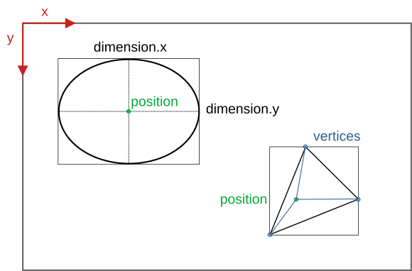
| Type | Constraint | Default | Unit | Required | Availability | Remarks |
|---|---|---|---|---|---|---|
| float | >= 0 && <= frame width | 0. | pixel | no | >= v3 | pixels |
| float | [0., 1.] | 0. | - | no | >= v3 | normalized |
Defines the x-position of the measurement field.
| Type | Constraint | Default | Unit | Required | Availability | Remarks |
|---|---|---|---|---|---|---|
| float | >= 0 && <= frame height | 0. | pixel | no | >= v3 | pixels |
| float | [0., 1.] | 0. | - | no | >= v3 | normalized |
Defines the y-position of the measurement field.
Specifies the dimensions of the measurement field. Depending on the configured shape different dimensions options may need to be set:
rectangle - x (width) and y (height)ellipse - x (diameter parallel to x-axis) and y (diameter parallel to y-axis)polygon - ignored.splines - ignored.normalized the dimension values are either pixel based or normalized to the range of [0., 1.] relative to the configured frame dimensions in the video format section.| Type | Constraint | Default | Unit | Required | Availability | Remarks |
|---|---|---|---|---|---|---|
| float | > 0 && x + width < frame width | 0. | pixel | no | >= v3 | pixels |
| float | [0., 1.] | 0. | - | no | >= v3 | normalized |
Defines the dimension in x of a rectangular or elliptical measurement field.
| Type | Constraint | Default | Unit | Required | Availability | Remarks |
|---|---|---|---|---|---|---|
| float | > 0 && y + height < frame height | 0 | pixel | no | >= v3 | pixels |
| float | [0., 1.] | 0 | - | no | >= v3 | normalized |
Defines the dimension in y of a rectangular or elliptical measurement field.
This section specifies the two-dimensional vertices that define the polygonal and spline based measurement fields. Their coordinates have to be specified relative to the point of origin set by the configured position.
rectangle - ignored.ellipse - ignored.polygon - at least three vertices are required.splines - at least four vertices are required.normalized the vertex values are either pixel based or normalized to the range of [0., 1.] relative to the configured frame dimensions in the video format section.| Type | Constraint | Default | Unit | Required | Availability | Remarks |
|---|---|---|---|---|---|---|
| float | vertex.x + position.x (>= 0 && <= frame width) | 0. | pixel | no | >= v3 | pixels |
| float | [0., 1.] | 0. | - | no | >= v3 | normalized |
Defines the x-position of the vertex relative to position.x.
| Type | Constraint | Default | Unit | Required | Availability | Remarks |
|---|---|---|---|---|---|---|
| float | vertex.y + position.y (>= 0 && <= frame height) | 0. | pixel | no | >= v3 | pixels |
| float | [0., 1.] | 0. | - | no | >= v3 | normalized |
Defines the y-position of the vertex relative to position.y.
| Type | Constraint | Default | Required | Availability |
|---|---|---|---|---|
| bool | - | false | no | >= v3 |
The flag specifies whether the values for position, dimension and individual vertices are pixel based or normalized to the range of [0., 1.] relative to the set video format dimensions. These values are either set in one format or the other. There is not mixing and matching.
Measurement fields can have a custom emissivity. The other radiation parameters - transmissivity and ambient temperature - are inherited from the overall thermal frame settings.
| Type | Constraint | Default | Required | Availability |
|---|---|---|---|---|
| float | [0.01, 1.1] | 1. | no | >= v2 |
Defines the emissivity for the measurement field. If left blank, the emissivity for the overall thermal frame settings is used instead. This is the default.
This section determines the configuration of the process interface (PIF). The first thing to do is specify the type and count of the used PIF. Then its individual channels can be configured.
For the analog inputs, the digital inputs, the analog outputs and the digital outputs multiple channels can be configured. For each of these channels their configuration has to be provided within individual <channel> tags. If no explicit configuration is provided for an available channel, the SDK will set its mode to off. The channels are each addressed by a combination of a <device_index> specifying the PIF device and a <pin_index> referring to the specific pin on this device.
Some PIFs feature a dedicated fail safe channel that can be switched on or off. In the case of stackable PIFs each device features a set of pins for this channel. If they are stacked together, these pins will always output the same signal. Therefore, ever only a maximum of one fail safe channel needs to be configured. The Fail Safe chapter offers more insights into the functionality of this channel type.
| Type | Constraint | Default | Required | Availability | Remarks |
|---|---|---|---|---|---|
| string | automatic | no | >= v2 | case insensitive |
Specifies the PIF device type.
Depending on the used camera different PIF devices types can be set:
Autonomous (Xi 80, Xi 320 MT, Xi 410(MT), Xi 1M)
automatic - The SDK uses the PIF device type and count stored in the on-device settings.none - No PIF device is used.internal - The built-in internal PIF is used.stackable - External stackable PIF(s) are used.Based on this setting the SDK will explicitly instruct the camera firmware to use/expect the specified PIF device type.
Non-autonomous (all other cameras)
automatic - The SDK uses the PIF device type detected by the firmware.none - No PIF is used.standard - A standard PIF is used.industrial_ma - An industrial PIF with current based analog outputs is used.industrial_mv - An industrial PIF with voltage based analog outputs is used.temperature_probe - Instead of a PIF an external temperature probe is used on the PIF connector.proprietary - The pins of the PIF connector are used directly.none, the SDK will adhere to it and will ignore attached PIF devices.automatic or if the configured PIF device type does not match the attached one, the SDK will still try to apply the channel configurations. This, however, may fail because not all of the PIF devices support the same analog output modes.none type and will ignore the channel configurations.| Type | Constraint | Default | Required | Availability |
|---|---|---|---|---|
| int | [1, 3] | 1 | no | >= v2 |
This option is only relevant for stackable PIFs. For all other PIF devices the SDK can derive it from the configured type:
none - 0This count specifies how many stackable PIFs can be accessed and configured through the SDK. The number of actual connected devices can be lower! Manipulating a device that is configurable but not actually connected has currently no tangible effects. This behavior will become relevant once the SDK supports autonomous on-device configurations.
2 but connect three stackable PIFs, the SDK will report that two PIFs are connected.All channels that are not explicitly configured will be set to the mode off by the SDK.
| Type | Constraint | Default | Required | Availability |
|---|---|---|---|---|
| int | [0, device_count) | 0 | no | >= v2 |
First part of the channel identification indicating on which PIF device its corresponding pins are located. Starts at 0 and is at its maximum one less than the device count.
| Type | Constraint | Default | Required | Availability |
|---|---|---|---|---|
| int | [0, pin_count) | 0 | no | >= v2 |
Second part of the channel identification indicating which pins on the PIF device correspond with the channel. Starts at 0 and is at its maximum one less than the pin count. The concrete pin count depends on the channel and PIF device type.
For more details on addressing channels please refer to the corresponding section in the Process Interface chapter.
Currently, all PIF devices feature analog inputs that can be used to read voltages between 0 and 10 V. The currently read voltages can always be accessed through the FrameMetadata object provided through the onThermalFrame() callback to IRImagerClients.
By specifying a <mode> the channels can be assigned a certain functionality. All other settings specify various parameters for these modes. UNIQUE modes can only be applied once across all channel types.
| Type | Constraint | Default | Required | Availability | Remarks |
|---|---|---|---|---|---|
| string | off | no | >= v2 | case insensitive |
Specifies the functionality assigned to this channel. The SDK currently supports the following modes:
off - The channel is switched off.ambient_temperature (UNIQUE) - The ambient temperature for the radiation parameters of the thermal frame is derived from the input voltage. The radiation parameters are updated at most every 500 ms.emissivity (UNIQUE) - The emissivity for the radiation parameters of the thermal frame is derived from the input voltage. The radiation parameters are updated at most every 500 ms tops.flag_control (UNIQUE) - The shutter flag can be controlled based on the input voltage.
uncommitted_value - The incoming voltage value is subjected to a custom linear transformation and is then provided by the SDK to all IRImagerClients along with its configured name and unit through the onPifUncommittedValue() callback.These settings define the parameters of the linear transformation that converts the measured input voltage U_in into the desired target values:
| Mode | Symbol | Transformation |
|---|---|---|
ambient_temperature | t_ambient | U_in[V] = gain[V/°C] * t_ambient[°C] + offset[V] |
emissivity | e | U_in[V] = gain[V] * e + offset[V] |
uncommitted_value | x | U_in[V] = gain[V/?] * x[?] + offset[V] |
| Type | Constraint | Default | Unit | Required | Availability |
|---|---|---|---|---|---|
| float | - | 1. | mode dependent | no | >= v2 |
Specifies the gain of the linear transformation.
| Type | Constraint | Default | Unit | Required | Availability |
|---|---|---|---|---|---|
| float | - | 0. | volt | no | >= v2 |
Defines the offset of the linear transformation.
Specifies the type of input voltages U_in for which actions are triggered.
| Mode | Action | low_active | !low_active |
|---|---|---|---|
flag_control | close the shutter flag | U_in < U_threshold | U_in >= U_threshold |
| open the shutter flag | U_in >= U_threshold | U_in < U_threshold |
| Type | Constraint | Default | Unit | Required | Availability |
|---|---|---|---|---|---|
| float | 0. | volt | no | >= v2 |
Defines the threshold voltage U_threshold. The configured value is automatically clipped to 0 - 10 V.
| Type | Constraint | Default | Required | Availability |
|---|---|---|---|---|
| bool | - | true | no | >= v2 |
Specifies whether the trigger is low active.
Specifies some additional information about an uncommitted value that will be passed alongside the transformed input voltage to the onPifUncommittedValue() callback of IRImagerClients.
| Type | Constraint | Default | Required | Availability |
|---|---|---|---|---|
| string | - | no | >= v2 |
Sets the name of the uncommitted value.
| Type | Constraint | Default | Required | Availability |
|---|---|---|---|---|
| string | - | no | >= v2 |
Specifies the unit of the uncommitted value.
On PIF devices that feature digital input channels binary voltage signals can be read. The current state of the signal - low/false or high/true - can always be accessed through the FrameMetadata object provided by the onThermalFrame() callback to IRImagerClients.
By specifying a <mode> the channels can be assigned a certain functionality. All other settings specify various parameters for these modes. UNIQUE modes can only be applied once across all channel types.
| Type | Constraint | Default | Required | Availability | Remarks |
|---|---|---|---|---|---|
| string | off | no | >= v2 | case insensitive |
Specifies the functionality assigned to this channel. The SDK currently supports the following modes:
off - The channel is switched off.flag_control (UNIQUE) - The shutter flag can be controlled based on the input signal.
Specifies based on which input signal S_in actions are triggered.
| Mode | Action | low_active | !low_active |
|---|---|---|---|
flag_control | close the shutter flag | S_in == low | S_in == high |
| open the shutter flag | S_in == high | S_in == low |
| Type | Constraint | Default | Required | Availability |
|---|---|---|---|---|
| bool | - | true | no | >= v2 |
Specifies whether the trigger is low active.
Depending on the PIF device type the analog output channels can provide voltage and/or current based signals.
By specifying a <mode> the channels can be assigned a certain functionality. All other settings specify various parameters for these modes. UNIQUE modes can only be applied once across all channel types.
| Type | Constraint | Default | Required | Availability | Remarks |
|---|---|---|---|---|---|
| string | off | no | >= v2 | case insensitive |
Specifies the functionality assigned to this channel. The SDK currently supports the following modes:
off - The channel is switched off.alarm - The or-combined state of potentially multiple alarm channels is output. <pif_analog_output>).external_communication - SDK clients can output a custom signal on the channel with the help of the setAoValue() method of the ProcessInterface.fail_safe (UNIQUE) - A heart beat signal is output on the channel indicating that the camera and processing pipeline are working correctly.flag_status (UNIQUE) - The current flag status is output on the channel.frame_sync (UNIQUE) - Outputs a pulse on the channel every time a new frame is captured.internal_temperature (UNIQUE) - The internal temperature is output on the channel. The internal temperature is equivalent to the value returned by the getTemperatureBox() method of the IRImager.measurement_field - The data point defined by the mode of the measurement field is output on the channel.| Type | Constraint | Default | Required | Availability | Remarks |
|---|---|---|---|---|---|
| string | 0-10v | no | >= v2 | case insensitive, no blanks |
Specifies the output output mode of the channel. Depending on the used PIF device one or more of the following modes are available:
0-10v - 0 - 10 V0-20ma - 0 - 20 mA4-20ma - 4 - 20 mAThese settings define the parameters of the linear transformation that converts data points into output values X_out. Depending on the chosen output mode [X_out] is either V or mA.
| Mode | Symbol | Transformation |
|---|---|---|
internal_temperature | t_internal | X_out[x] = gain[x/°C] * t_internal[°C] + offset[x] |
measurement_field | x_field | X_out[x] = gain[x/?] * x_field[?] + offset[x] |
x_field of a measurement field is provided depends on the mode setting of the measurement field.| Type | Constraint | Default | Unit | Required | Availability |
|---|---|---|---|---|---|
| float | - | 1. | mode and output mode dependent | no | >= v2 |
Specifies the gain of the linear transformation.
| Type | Constraint | Default | Unit | Required | Availability |
|---|---|---|---|---|---|
| float | - | 0. | output mode dependent | no | >= v2 |
Defines the offset of the linear transformation.
Defines which statistical value of which measurement field should be output.
| Type | Constraint | Default | Required | Availability |
|---|---|---|---|---|
| int | [0, count of configured measurement fields) | 0 | no | >= v3 |
Identifies the measurement field whose data point should be output. The index 0 refers to the first measurement field specified in the configuration and adheres to the sequence in which they are defined.
If there are three measurements fields configured, then 0 refers to the first, 1 to the second and 2 to the third field specified.
| Type | Constraint | Default | Required | Availability | Remarks |
|---|---|---|---|---|---|
| string | mean | no | >= v3 | case insensitive |
Specifies which statistical value of the processed measurement field should be output. Available options are:
min - minimum temperature in °C.max - maximum temperature in °C.mean - arithmetic mean temperature in °C.median - median temperature in °C.These configuration options specify what values X_out are output for different states or events. There values are automatically clipped to the limits of the set output mode.
| Mode | active | intermediate | inactive |
|---|---|---|---|
alarm | at least one alarm channel is Active | no alarm channel is Active | |
fail_safe | pulse height | - | - |
flag_status | flag is closed | flag is moving | flag is open |
frame_sync | pulse height | - | - |
| Type | Constraint | Default | Unit | Required | Availability |
|---|---|---|---|---|---|
| float | 10. | output mode dependent | no | >= v2 |
Defines the output level for an "active" event/state. Its value is automatically clipped to the limits of the set output mode.
| Type | Constraint | Default | Unit | Required | Availability |
|---|---|---|---|---|---|
| float | 10. | output mode dependent | no | >= v2 |
Defines the output level for an "intermediate" event/state. Its value is automatically clipped to the limits of the set output mode.
| Type | Constraint | Default | Unit | Required | Availability |
|---|---|---|---|---|---|
| float | 0. | output mode dependent | no | >= v2 |
Defines the output level for an "inactive" event/state. Its value is automatically clipped to the limits of the set output mode.
By specifying a <mode> the channels can be assigned a certain functionality. All other settings specify various parameters for these modes. UNIQUE modes can only be applied once across all channel types.
| Type | Constraint | Default | Required | Availability | Remarks |
|---|---|---|---|---|---|
| string | off | no | >= v2 | case insensitive |
Specifies the functionality assigned to this channel. The SDK currently supports the following modes:
off - The channel is switched off.alarm - The or-combined state of potentially multiple alarm channels is output. <pif_digital_output>).external_communication - SDK clients can output a custom signal on the channel with the help of the setDoValue() method of the ProcessInterface.fail_safe (UNIQUE) - A heart beat signal is output on the channel indicating that the camera and processing pipeline are working correctly.flag_status (UNIQUE) - The current flag status is output on the channel.frame_sync (UNIQUE) - Outputs a pulse on the channel every time a new frame is captured.These settings adjust the output signal.
| Mode | low_active | !low_active |
|---|---|---|
flag_status | low if flag is closed | high if flag is closed |
| Type | Constraint | Default | Required | Availability |
|---|---|---|---|---|
| bool | - | true | no | >= v2 |
Defines whether a high or low signal is output on an "active" state and/or event.
alarm - if set to true, the output will be low when at least one alarm is active.flag_status - if set to true, the output will be low when the shutter flag is closed.There is always only one fail safe channel available per PIF or per set of stackable PIFs. Please refer to the Fail Safe chapter for more information about the signal that is provided on this channel.
This configuration will only be applied, if a fail safe channel is available.
| Type | Constraint | Default | Required | Availability | Remarks |
|---|---|---|---|---|---|
| string | off | no | >= v2 | case insensitive |
Specifies the functionality assigned to this channel. The SDK currently supports the following modes:
off - The channel is switched off.on - The channel is switched on.The calibration files for a device consists out of up to three different file types:
Cali-<Serial Number>.xml specifying available optics, temperature ranges, video formats and other device specific parameters.Cali-<Serial Number>-<...>.datKennlinie-<Serial Number>-<...>.prn specifying characteristic curves.How To Get Them
The SDK automatically tries to acquire missing calibration files. By default it attempts to copy them from a local source directory on the filesystem. The location of this source directory is not set out of the box. When that fails the SDK tries to download the missing files from Optris servers.
Sdk class. Refer to the chapter calibration file acquisition details.The automatically downloaded or copied files will be placed in the user settings directory:
<Custom Data Directory>/Cali/<User AppData>\Roaming\Imager\Cali\ on Windows~/.config/optris/Cali/ on LinuxSDK Search Hierarchy
User data directory
<Custom Data Directory>/Cali/<User AppData>\Roaming\Imager\Cali\ on Windows~/.config/optris/Cali/ on LinuxThese files contain corrections for the temperature calculation when the emissivity is not 1. They consist of two different types of files:
Norm.xml defining which normalization file apply for a specific camera type.Norm-<Id>.prn containing the corrections.How To Get Them
These files are automatically installed.
SDK Search Hierarchy
Norm\ subfolder in the working directory of the application.<Custom Data Directory>/Cali/Norm/<User AppData>\Roaming\Imager\Cali\Norm\ on Windows~/.config/optris/Cali/Norm/ on Linux<SDK Install Directory>\norm\ on Windows/usr/share/otcsdk/norm/ on LinuxThe formats definitions file specifies what video formats are supported by the different devices. It also tells the SDK how to process received data frames.
File Name
Formats.def
How To Get It
The file is automatically installed. If lost, you can download it from an Optris server.
SDK Search Hierarchy
<Custom Data Directory><User AppData>\Roaming\Imager\ on Windows~/.config/optris/ on Linux<SDK Install Directory>\ on Windows/usr/share/otcsdk/ on LinuxPlain CVS files specifying the color palettes used to convert thermal frames into false color images. For more details on the used file format can be found here.
File Name
<Palette Name>.csv
How to get it
These files are automatically installed.
<Custom Data Directory>/palettes/<User AppData>\Roaming\Imager\palettes\ on Windows~/.config/optris/palettes/ on Linux<SDK Install Directory>\palettes\ on Windows/usr/share/otcsdk/palettes/ on LinuxThis file contains dead pixels detected by the SDK.
File Name
DP-<Serial Number>.dat
How To Get It
The file is automatically generated by the SDK once a dead pixel is detected.
SDK Search Hierarchy
<Custom Data Directory>/DynamicDeadPixels/<User AppData>\Roaming\Imager\DynamicDeadPixels\ on Windows~/.config/optris/DynamicDeadPixels/ on LinuxThe log files contain the log messages generated by the SDK. With the help of the Sdk::init() and Sdk::configureLogger() methods you control the log verbosity and define a prefix for the log filenames.
File Name
<Log File Prefix>_<YYYY_MM_DDThh-mm-ss>.log
<Log File Prefix> is defined by the value of the logFilePrefix argument that was passed to the Sdk::init() or Sdk::configureLogger() methods. If an empty string was given, it defaults to OtcSDK. The rest of the filename is comprised of an timestamp denoting the point in time when the file was created (local time).
How To Get It
Log files are created when their corresponding verbosity is not set to Off.
Location
<Custom Data Directory>/Logs/<User AppData>\Roaming\Imager\Logs\ on Windows~/.config/optris/Logs/ on LinuxInstead of — or in addition to — writing log messages to files and the console, you can register a callback function using Sdk::setLogCallback() to receive every log message programmatically. This is useful for integrating the SDK into applications that have their own logging system.
The callback receives two parameters:
verbosityLevel — an integer indicating the severity: 0 = Error, 1 = Warning, 2 = Info, 3 = Debug, 4 = Trace.message — the log message text.When the exclusive parameter is set to true, the SDK suppresses its own file and screen output, allowing the callback to take full ownership of log routing. When set to false (default), the callback receives messages in addition to normal file and screen output.
C++ Example
C# Example
Python Example
To remove the callback, call Sdk::setLogCallback(nullptr) (C++), Sdk.setLogCallback(null) (C#), or Sdk.setLogCallback(None) (Python).